Timer And Contactor R Relay Diagram - Contactor Vs Relay Allied Electronics Automation : A contactor joins 2 poles together, without a common circuit between them, while a relay has a common contact that connects to a neutral position.
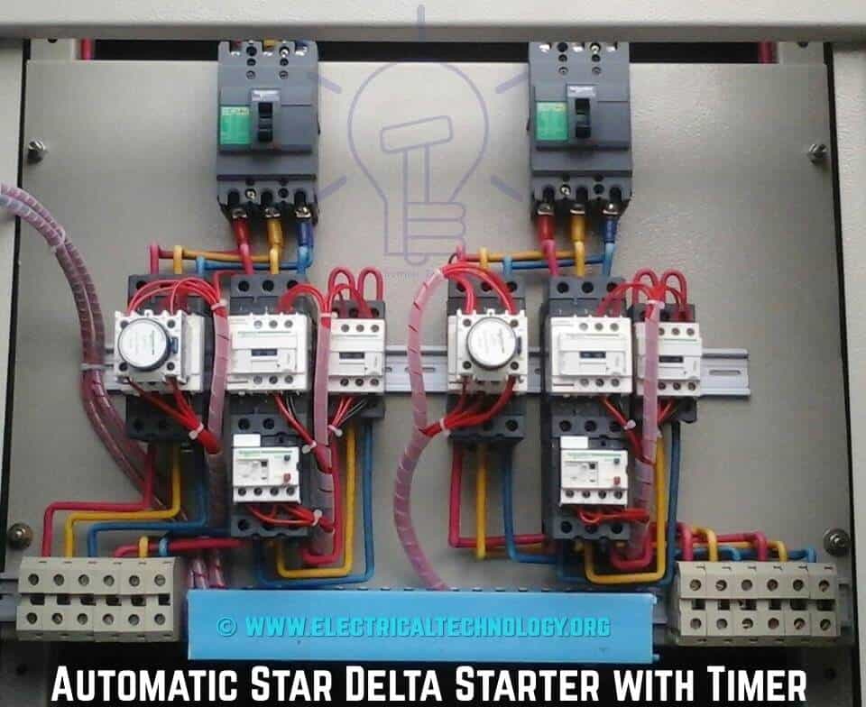
Timer And Contactor R Relay Diagram - Contactor Vs Relay Allied Electronics Automation : A contactor joins 2 poles together, without a common circuit between them, while a relay has a common contact that connects to a neutral position.. When designing circuits using time delay relays, questions such as what initiates a time delay relay, does the timing start with the application or release of voltage, when is the output relay energized, etc., must be asked. The timer relay disconnects the connection from the contactor star while running the delta contestor so that the current flowing on the motor changes from (main star) to (main + delta), with windings w2, u2, v2 for the delta contactor. Relay logic basically consists of relays wired up in a particular fashion to perform the desired switching operations. Time delay relays are simply control relays with a time delay built in. Contactors are used in control circuits with both low and high ampere capacity that is between 15a to 12500a.
A wiring diagram is a simplified traditional pictorial depiction of an electrical circuit. Hence time t=120k*470uf=6 2 seconds~1 minute (approximately). A simple circuit diagram either of the two start buttons will close the contactor, either of the stop buttons will open the contactor. Refer to the lighting control contactor wire diagram for the specific photocell voltage (control voltage). A normally closed relay will switch power off for a circuit when the coil is activated.
Refer to the lighting control contactor wire diagram for the specific photocell voltage (control voltage).
Control relays and timers eaton's mission is to improve the quality of life and the environment through the use of power management technologies and services. Thus relay will be on for required amount of time set by the user using pot and then it is switched of automatically. The main difference between the contactor and relay is that, contactor is a high power device while relay is a low power device. A timing diagram is a graph that shows the status of the timer to the timing device in relation to the performance of the contact or output of the timer. Such relays are called time delay relays. A 12v relay is used to drive the ac load connected at the output. Set the time delay period t1 on each timer to the same value. In electrical engineering, a switch is an electrical component that can break an electrical circuit, interrupting the current or diverting it. This tool is a protection or security device that is installed after a distribution device. Operationally, it works the same way. A contactor joins 2 poles together, without a common circuit between them, while a relay has a common contact that connects to a neutral position. In stock and ready to ship. It reveals the components of the circuit as simplified shapes, and also the power and signal connections in between the tools.
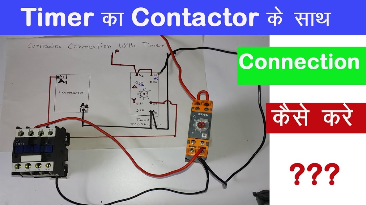
Wire the three time delay relays & traffic signal per the following diagram and the system will operate as described below. Time delay relays are simply control relays with a time delay built in. Timer has two element, timer and relay. 5 pin relay 5 pin relays provide 2 pins (85 & 86) to control the coil and 3 pins (30, 87 & 87a) which switch power between two circuits. I want to know the wiring diagram of the digital timer with contactor in light control panel.

Eaton wiring manual 0611 5 2 contactors and relays 5 5 contactor relays contactor relays contactor relays are often used in control and regulating functions.
Clap switch circuit using ic 555 timer & without timer. Time delay relays are simply control relays with a time delay built in. Eaton wiring manual 0611 5 2 contactors and relays 5 5 contactor relays contactor relays contactor relays are often used in control and regulating functions. Relay logic basically consists of relays wired up in a particular fashion to perform the desired switching operations. This simple solution can be done with one interval on (td1) & two single shot (td2 & td3) time delay relays. The circuit that applies the voltage to the coil is referred to as the control circuit , because it controls the main device that the contactor or relay is switching. How to wire a photocell with a relay contactor for outsiden customer question. It shows the components of the circuit as simplified shapes, and also the power as well as signal connections in between the gadgets. How do you want this circuit run. If you can give me placement of all the parts, i will draw up a detailed diagram for you. Wiring diagram book a1 15 b1 b2 16 18 b3 a2 b1 b3 15 supply voltage 16 18 l m h 2 levels b2 l1 f u 1 460 v f u 2 l2 l3 gnd h1 h3 h2 h4 f u 3 x1a f u 4 f u 5 x2a r. This creates a basic memory function the relay ' remembers'. I want to know the wiring diagram of the digital timer with contactor in light control panel.
This sample is particularly useful since you can replace one relay (as shown in the diagram) with a physical light switch. Wiring diagram book a1 15 b1 b2 16 18 b3 a2 b1 b3 15 supply voltage 16 18 l m h 2 levels b2 l1 f u 1 460 v f u 2 l2 l3 gnd h1 h3 h2 h4 f u 3 x1a f u 4 f u 5 x2a r. The main difference between the contactor and relay is that, contactor is a high power device while relay is a low power device. So it may be the motor switch, or it may be an actual latching google on/off contactor schematics and you will get some good wiring diagrams. Timer has two element, timer and relay.
Contactors are used in control circuits with both low and high ampere capacity that is between 15a to 12500a.
It reveals the components of the circuit as simplified shapes, and also the power and signal connections in between the tools. The main difference between the contactor and relay is that, contactor is a high power device while relay is a low power device. Our channel provide the best electrical video tutorials which is about electrical wiring ,home wiring ,transmission line hv, mv, lv, motor control ,sequence. Operationally, it works the same way. A timing diagram is a graph that shows the status of the timer to the timing device in relation to the performance of the contact or output of the timer. The timer relay disconnects the connection from the contactor star while running the delta contestor so that the current flowing on the motor changes from (main star) to (main + delta), with windings w2, u2, v2 for the delta contactor. The diagram has two graphs, one is used to represent the input signal to the timing device; Wiring diagram book a1 15 b1 b2 16 18 b3 a2 b1 b3 15 supply voltage 16 18 l m h 2 levels b2 l1 f u 1 460 v f u 2 l2 l3 gnd h1 h3 h2 h4 f u 3 x1a f u 4 f u 5 x2a r. Clap switch circuit using ic 555 timer & without timer. The circuit that applies the voltage to the coil is referred to as the control circuit , because it controls the main device that the contactor or relay is switching. Assortment of 12 volt relay wiring diagram. A normally open relay will switch power on for a circuit when the coil is activated. In electrical engineering, a switch is an electrical component that can break an electrical circuit, interrupting the current or diverting it.
Komentar
Posting Komentar